

MYZR-I.MX6-EK140P
1пЉЪSingle Core/Commercial grade
2пЉЪNXP i.MX6ULL
3пЉЪARM Cortex-A7
4пЉЪ256MB DDR3
5пЉЪ4GB EMMC
product detailпЉЪ
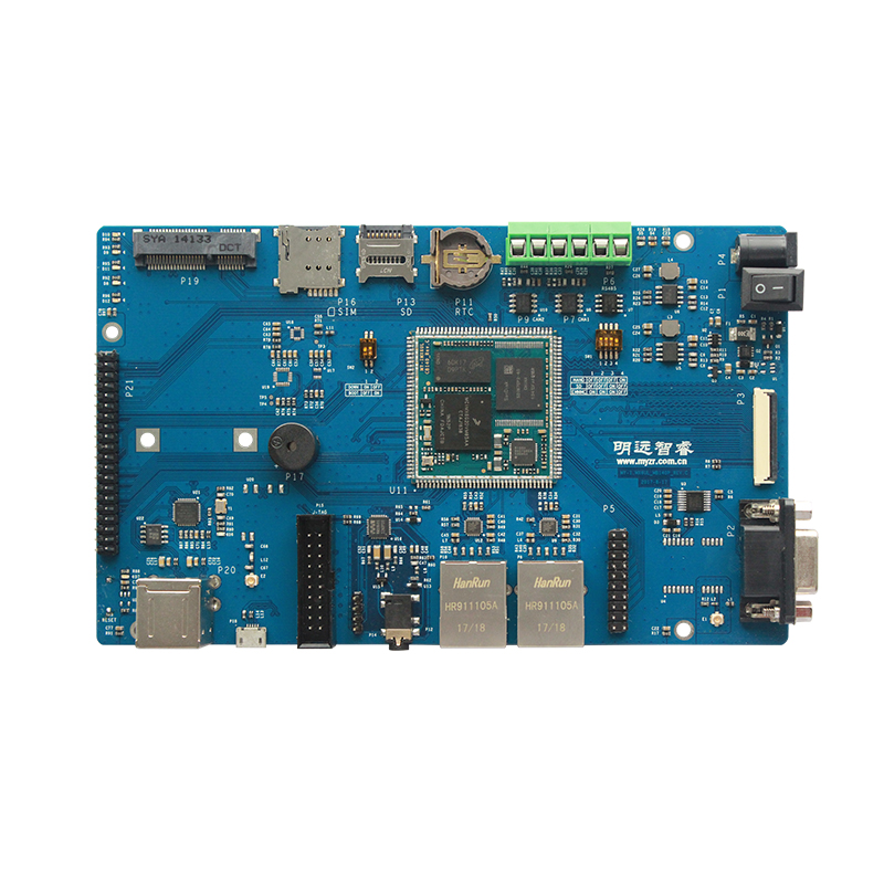
Overview of interfaces
IMX6ULL-EK140P Front view

IMX6ULL-EK140P Rear view

Interface function
5V_IN
The acceptable input voltage for MY-IMX6-MB140P is 5V and the current is 2.5A and above.
| Silk screen | Interface | Function | Interface property |
|---|---|---|---|
| P4 | 5V_IN | Voltage input | Internal positive and external negative Jack |
-
Schematic and functional signals

U1
| Interface no. | Signal name | Interface pin no. | Signal name | |
|---|---|---|---|---|
| 1 | VDD | 4 | DOUT | |
| 2 | GND1 | 5 | SENSE/CD | |
| 3 | GND2 |
SWITCH
| Silk screen | Interface | Function | Status attribute |
|---|---|---|---|
| P1 | SWITCH | Power switch | —пЉМcloseпЉЫOпЉМdisconnect |
-
Schematic
18/24bit RGB
| Silk screen | Interface | Function | Interface type |
|---|---|---|---|
| P3 | RGB | RGB crystal liquid | Standard 0.5mm FPC seat, 40PIN |
RGB crystal liquid is 24bit modeпЉМcompatible to 18bit/16bit mode,through which RGB resistance screen panel and RGB capacitor screen panel in different sizes and specifications produced by MYZR can be connectedпЉМRGB interface block is build with connector importedпЉМabandon the cheap drawer type produced domesticallyпЉМwhich is opposite press type to ensure easier installation,better performance and connectivity.
-
Schematics and signal definitions3

| Pin | Signal | Description |
|---|---|---|
| P3-08 | LCD_HSYNC | LCD row clock |
| P3-18 | LCD_PCLK | LCD dot clock |
| P3-19 | PWM4 | LCD backlight adjustment |
| P3-20 | LCD_VSYNC | LCD frame clock |
| P3-21 | LCD_DE | Data Input Enable |
| P3-30 | TOUCH_nEINT1 | GPIO control |
| P3-31 | TOUCH_nEINT2 | GPIO control |
| P3-32 | TOUCH_SCL | I2C clock |
| Others | LCD_DATA* | LCD data |
RS232
| Silk screen | Interface | Function | Interface type |
|---|---|---|---|
| P2 | RS232 | debug serial port | 3 thread standard RS232 port |
-
Schematic and functional signals

| Interface no. | Signal name | Interface no. | Signal name | |
|---|---|---|---|---|
| 1 | C1+ | 2 | V+ | |
| 3 | C1- | 4 | C2+ | |
| 5 | C2- | 6 | V- | |
| 7 | T2OUT | 8 | R2IN | |
| 9 | R2OUT | 10 | T2IN | |
| 11 | T1IN | 12 | R1OUT | |
| 13 | R1IN | 14 | T1OUT | |
| 15 | GND | 16 | VCC |
GPS
| Silk screen | Interface | Function | Interface type |
|---|---|---|---|
| E1 | GPS_ANT | connect GPS antenna | Standard GPS antenna pedestal |
-
Schematic and signals

| Pin | Pin function |
|---|---|
| UART4_RXD | TxD1 |
| UART4_TXD | RxD1 |
UART6/7/8
| Silk screen | Interface | Function | Interface type |
|---|---|---|---|
| P5 | UART6/7/8 | Reserve serial port | Standard 2.54 double row 20PIN |
-
Schematic and functional signals

| Interface no. | Signal name | Interface no. | Signal name | |
|---|---|---|---|---|
| 1 | GND | 2 | GND | |
| 3 | ENET2_RXER | 4 | UART8_RTS | |
| 5 | ENET2_RXD1 | 6 | UART6_RXD | |
| 7 | ENET2_TX_CLK | 8 | UART8_CTS | |
| 9 | ENET2_RXD0 | 10 | UART6_TXD | |
| 11 | ENET2_TXEN | 12 | UART8_RXD | |
| 13 | ENET2_CRS_DV | 14 | UART7_TXD | |
| 15 | ENET2_TXD1 | 16 | UART8_TXD | |
| 17 | ENET2_TXD0 | 18 | UART7_RXD | |
| 19 | GEN_3V3 | 20 | GEN_3V3 |
ETH
| Silk screen | Interface | Function | Interface type |
|---|---|---|---|
| P10 | ETH1 | 10/100-Mbps Ethernet | RJ-45 |
| P8 | ETH2 | 10/100-Mbps Ethernet | RJ-45 |
Note: To use ETH2, please short the P5 (UART6 / 7/8) one by one
-
Schematic and functional signals

ETH1

ETH2
| Interface no. | Signal name | Interface no. | Signal name | |
|---|---|---|---|---|
| 1 | TD+ | 7 | NC | |
| 2 | TD- | 8 | GND | |
| 3 | RD+ | 9 | LED_G+ | |
| 4 | MTD | 10 | LED_G- | |
| 5 | MRD | 11 | LED_Y- | |
| 6 | RD- | 12 | LED_Y+ |
-
Schematic and functional signals

ETH1

ETH2
Note: To use ETH2, please short the P5 (UART6 / 7/8) one by one.
| Pin | Pin function | Pin | Pin function | |
|---|---|---|---|---|
| ENET_MDIO | MDIO | ENET_MDC | MDC | |
| ENET1_RXD0 | RXD0/MODE0 | ENET1_RXD1 | RXD1/MODE1 | |
| ENET1_TXD0 | TXD0 | ENET1_TXD1 | TXD1 | |
| ENET1_CRS_DV | CRS_DV/MODE2 | ENET1_TXEN | TXEN | |
| ENET1_TX_CLK | XTAL1/CLKIN | ENET1_RXER | RXER/PHYAD0 | |
| ENET1_nRST | RST | SNVS_TAMPER2 | INT/REFCLKO |
HP/MIC
| Silk screen | Interface | Function | Interface type |
|---|---|---|---|
| P12 | HP/MIC | Speech output | Standard 3.5mm headphone audio stand |
-
Schematic and signals

| Pin | Pin function | Pin | Pin function | |
|---|---|---|---|---|
| AUD_INT | ADCLRC/GPIO1 | SAI2_SYNC | DACLRC | |
| SAI2_BCLK | BCLK | SAI2_RXD | ADCDAT | |
| SAI2_TXD | DACDAT | SAI2_MCLK | MCLK | |
| AUDIO_SCL | SCLK | AUDIO_SDA | SDIN |